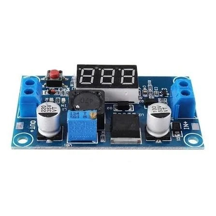
LM2596 Buck Converter Module with Digital Display
The LM2596 Buck Converter Module with Display is an adjustable DC-DC step-down power supply module designed to convert a higher DC input voltage into a lower, stable output voltage. It uses the popular LM2596 switching regulator and includes a built-in digital display for convenient monitoring of output voltage.
This adjustable buck converter is useful for Arduino, ESP32, ESP8266, Raspberry Pi projects, sensors, LED circuits, robotics, DIY electronics, battery-powered projects, and embedded systems. The output voltage can be adjusted using the onboard potentiometer, making it easy to obtain the required voltage for different electronic components.
The digital display allows you to check the output voltage directly from the module without requiring an external multimeter for routine adjustment. Its compact size and screw terminal connections make it convenient for prototyping, laboratory experiments, repair work, and electronics projects.
For Bangladeshi students, engineers, makers, and electronics technicians, the LM2596 DC-DC Buck Converter Module is a practical solution when a reliable lower DC voltage is required from a higher DC supply.
Features:
- Adjustable DC-DC step-down voltage converter
- Based on the LM2596 switching regulator
- Built-in digital voltage display
- Adjustable output using onboard potentiometer
- Suitable for Arduino, ESP32, ESP8266 and other microcontroller projects
- Useful for robotics, sensors, LED projects and DIY electronics
- Compact and easy-to-use PCB module
- Screw terminals for convenient input and output connections
- Suitable for laboratory, prototyping and repair applications
- Efficient switching regulator design compared with simple linear regulators
Specifications:
| Specification | Details |
|---|---|
| Product Type | Adjustable DC-DC Buck Converter Module |
| Main IC | LM2596 |
| Conversion Type | Step-Down / Buck |
| Input | DC voltage |
| Output | Adjustable DC voltage |
| Voltage Adjustment | Onboard potentiometer |
| Display | Digital voltage display |
| Connector | Screw terminal |
| Application | Electronics, Arduino, Robotics, DIY Projects |
| Module Type | Non-isolated DC-DC converter |
| PCB | Compact module board |
| Regulation | Switching voltage regulation |
Important: Exact input voltage range, output voltage range, maximum current, display accuracy, and efficiency can vary between LM2596 module versions and manufacturers. Check the specific module's PCB markings or seller specifications before designing a circuit around its limits.
How to Use
- Connect the DC input to the IN+ and IN− terminals.
- Connect a multimeter to the output for initial verification.
- Adjust the onboard potentiometer slowly.
- Set the required output voltage.
- Connect your load to OUT+ and OUT−.
- Verify that the output voltage is suitable for your circuit before connecting sensitive electronics.
Safety Tip
Always confirm the polarity and voltage before connecting the module to Arduino, ESP32, sensors, ICs, or other sensitive components. Do not exceed the specific module's rated input, output, current, or thermal limits.
Related Products


